
GSS402 RF Cable
GSS402 RF Cable
detailed information
5GSS402 RF Cable Low-Loss, Stable-Phase RF Cable
Product Appearance
PIN:24.06.001.0011
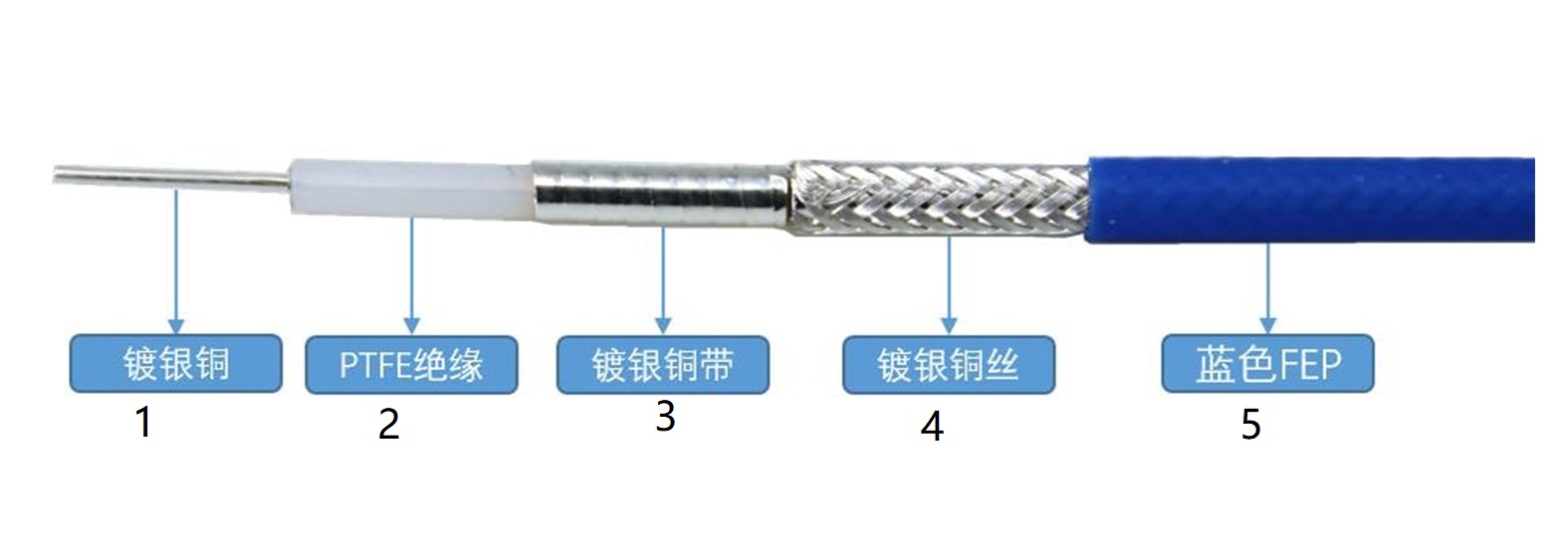
| Structure | Dimensions (mm) | Tolerances | Material | |
| 1 | Center Conductor | 0.92 | ±0.02 | Silver-plated copper |
| 2 | Dielectric | 2.98 | ±0.05 | PTFE |
| 3 | Outer Conductor | 3.13 | ±0.10 | Silver-plated copper tape |
| 4 | Outer Shield | 3.50 | ±0.10 | Silver-plated copper wire |
| 5 | Jacket | 4.00 | ±0.10 | Blue FEP |
Product Features
Low standing wave ratio
High cost-effectiveness
Typical Applications
Phased-array radar
Internal interconnects
Mechanical and Environmental Properties
Minimum bending radius, installation (mm) :20
Bending radius, repeated bending (mm):40
Weight (g/m):45
Temperature range, installation and use (°C):-55 to +150
Temperature range, storage (°C):-65 to +150
Electrical Performance
Operating Frequency (GHz):18
Characteristic Impedance (Ohms):50
Propagation Rate:70%
Shielding Efficiency (dB):100
Dielectric Strength (V, DC):500
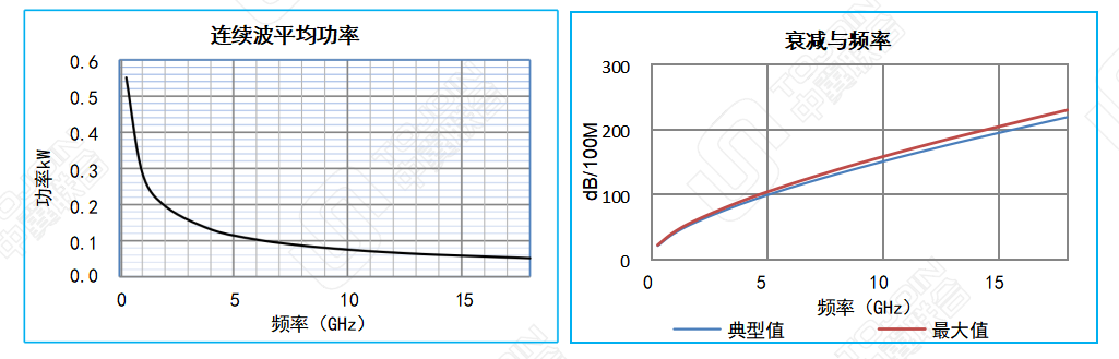
Attenuation (Typ.@25ºC&VSWR=1.0) Transmission Power (Typ.@40°C and standard atmospheric pressure) | ||||||||||
| Frequency MHz | 300 | 1000 | 2000 | 4000 | 6000 | 8000 | 10000 | 12000 | 14000 | 18000 |
| dB/100 m | 20.4 | 38.9 | 57.3 | 85.5 | 109.0 | 130.0 | 149.4 | 167.6 | 185.1 | 218.0 |
| Average Power kW | 0.551 | 0.288 | 0.196 | 0.131 | 0.103 | 0.086 | 0.075 | 0.067 | 0.061 | 0.051 |
| K1=1.1098110 K2= 0.0038390 | ||||||||||
| Calculation formula = K1 * √FMHz + K2 * FMHz | ||||||||||